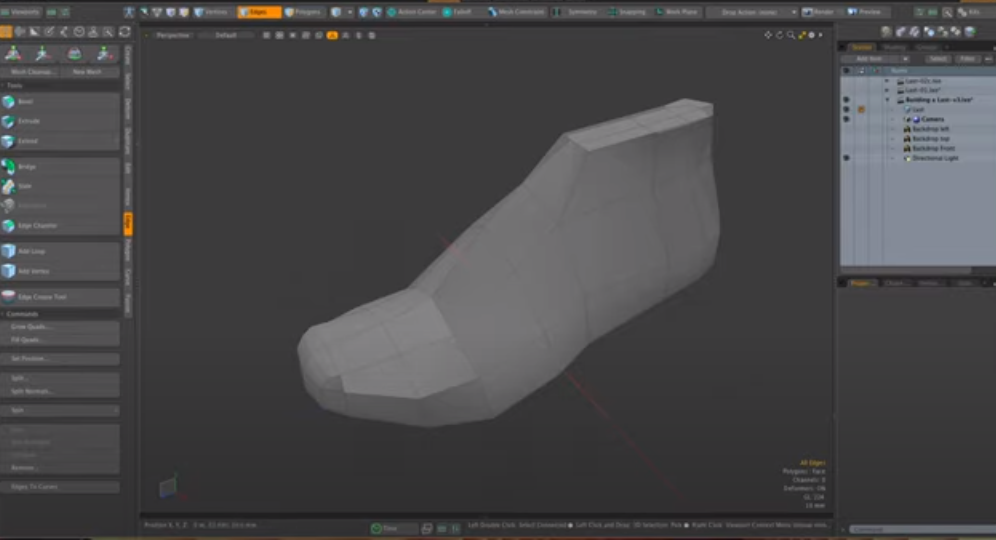
Modo is a 3D modeling, simulation, and rendering application developed by The Foundry. Modo is built on Lagoa's high-end kernel, with Lagoa meaning "the ocean" in Portuguese.
This software was developed specifically for entertainment and visual effects (VFX) productions. It has all the standard modeling and texturing/painting tools you would expect it to have. There are other unique features too, like a job manager, which keeps track of the entire production pipeline of your project.
Product design is an integral part of our daily lives, from traditional retail to modern fashion. Today, we have many tools available to make product design easier and faster than ever before. So, let's take a look at how you can use the latest productivity tools in Modo to improve your workflow and increase your efficiency.
There are some restrictions on the export of the glTF format. You can export transparent plastic material by using the diffuse color only.
When you export a glTF model from this application, you can import it into any other application that supports the glTF format, such as the p3d.in 3D model hosting and visualization framework.
Ready to export your model? Click File, then export. Choose a file type from the dropdown menu, give it a name and location, and click Save.
Unit size: If a scene is not utilizing scene units, it is best to set the unit size because it tells the program how big your geometry should be in real-life measurements.
The texture resolution in dpi: Texture resolution in dots per inch (dpi) varies for each part. The higher the dpi, the crisper your textures will be. However, your file size will also increase if you use a large dpi.
Ambient occlusion: The baked texture will include it when you turn on ambient occlusion
Use Draco to compress the geometry: Compressing a scene using Draco will significantly reduce the file size of the geometry but will not affect texture quality.
The number of samples: A low value will result in an image containing excessive amounts of noise. Raising the value of a commodity increases its time to export it.
Please choose only one option (Geometry Nodes or Textures): It is impossible to apply both Geometry nodes (bubbles, flakes, displacement) and textures on a single part. This decision will determine whether you prioritize the effects of one type over another.
You can use your 3D application's exporter to generate a suitable glTF file and upload the model to p3d.in, you can upload any number of files with a size of up to 300 MB.
p3d.in support a wide range of 3D file formats including:
The modeling section of this tutorial is going to be kept very simple. We'll use a basic shoe as an example, but we'll use techniques that you can apply in virtually any 3D package.

You can use polygon edges to quickly select complex objects and create new geometry from model edges. There are two different polygon edges in Modo: both are called polygon edges, but they work differently.
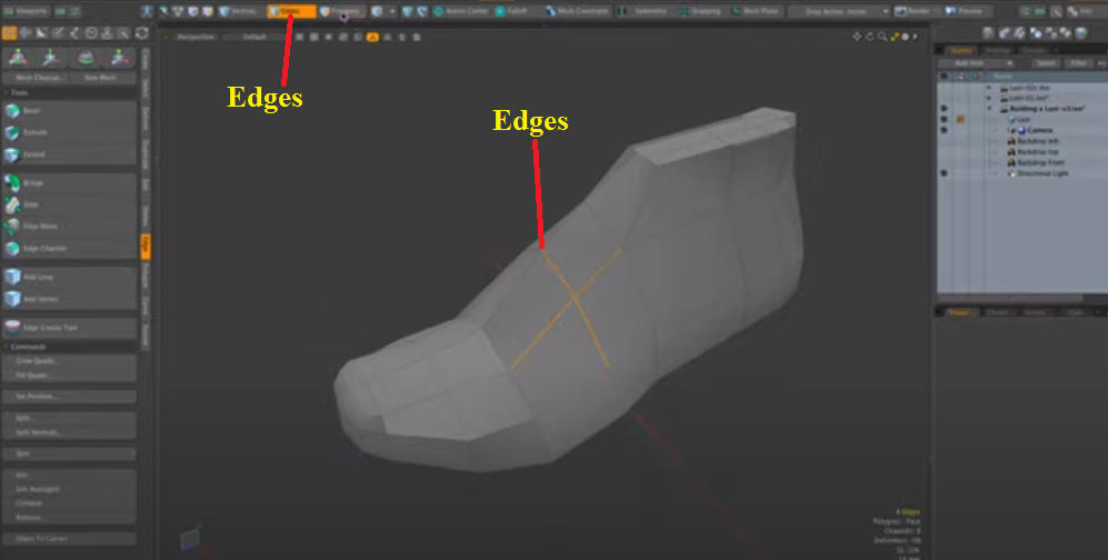
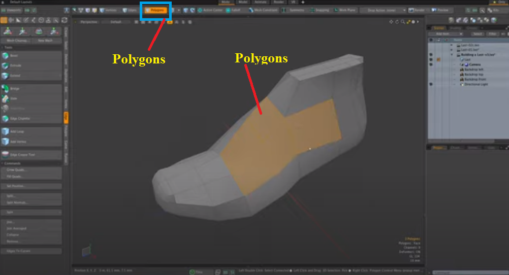
It's easy to select multiple polygon objects in the 3D view. Just go into polygon mode and when your mouse is over a polygon, it will turn red. Then, you click and hold down the mouse button and drag around to paint-select multiple polygons.
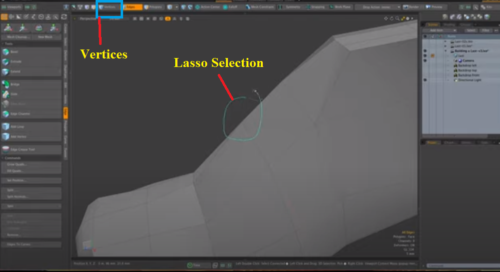
The Lasso Selection tool is a great way to make complex selections within Modo. You can use it in the same way as in any other application. The Lasso Selection tool generally works best when selecting a part or edge loop with no obvious start point, such as a curved edge.
Selecting objects with the Lasso tool is as simple as selecting them with the Marquee Selection tool. The only difference is that you have to outline the area of interest with your mouse instead of dragging a box around it.
The same is true for vertices. If you want to select something tricky or difficult to see from an odd angle, you can always use the Lasso Selection tool. The Lasso tool will always select through to that particular vertex, regardless of what component mode you're in your workflow.
The Move tool, the W-key, is used to move the center of your object. The object's center is a special pivot point that is the basis for the rotation and scale transformation tools. It's usually located at the lowest point of your model, in the middle of the bottom edge.
If you haven't yet chosen an object, you can use this tool to drag a selection rectangle around one or more objects and groups.
In this step, we'll use the moving tool: the W-key.
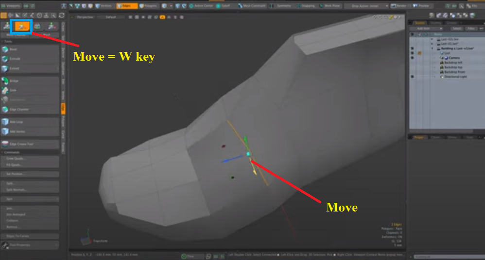
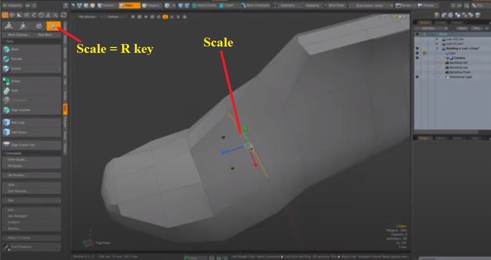
The Scaling tool is used to increase or decrease the size of an object on the x, y, and z axes. This tool is useful for increasing or decreasing an object size in all directions. For example, if you want to increase the size of a head by 50%, you can use the Scale tool to increase its size in all directions.
When you want to scale an object with precision, there are several different ways to accomplish this. The Modo Scale tool is one of these ways. There are two ways in which you can use the Scale tool.
Uniform way: The first is to select a component (vertex, edge, or poly) and click on the Scale tool in the Items tab. You activate the tool by pressing R on your keyboard. You can achieve uniform scaling when you’ve activated the tool by clicking anywhere in the viewport.
You can achieve relative scaling by holding down Shift and clicking anywhere in the viewport (relative to the selected component before entering the scale mode). You can also change from uniform to relative scaling by pressing X on your keyboard after activating the scale mode.
Non-uniform way: To use it in a non-uniform way, click and hold on a component or anywhere on your mesh. You can drag it outwards or inwards using your left mouse button. If you want to scale non-uniformly, hold down Shift while dragging outwards or inwards with your left mouse button. The non-uniform way will scale everything uniformly to where you started dragging your mouse.
For this step, the scale, or R-key, is the tool you use to access the scale of your model.
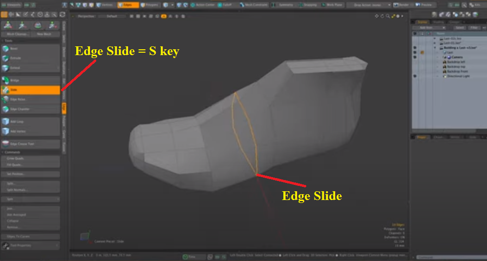
The Edge Slide tool allows you to reshape edges and edge loops quickly.
Select an edge or edge loop and press S to create a smooth edge. Move your mouse to slide the selected edges to use the tool. The edges will influence each other as you move them around.
You can adjust the falloff of the slide by adjusting the radius value in the Tool Properties panel. Depending on your keyboard layout, you can also toggle between pushing and pulling edges with the +/- buttons, or by holding down shift/control (depending on your keyboard layout).
Here are the basic steps:
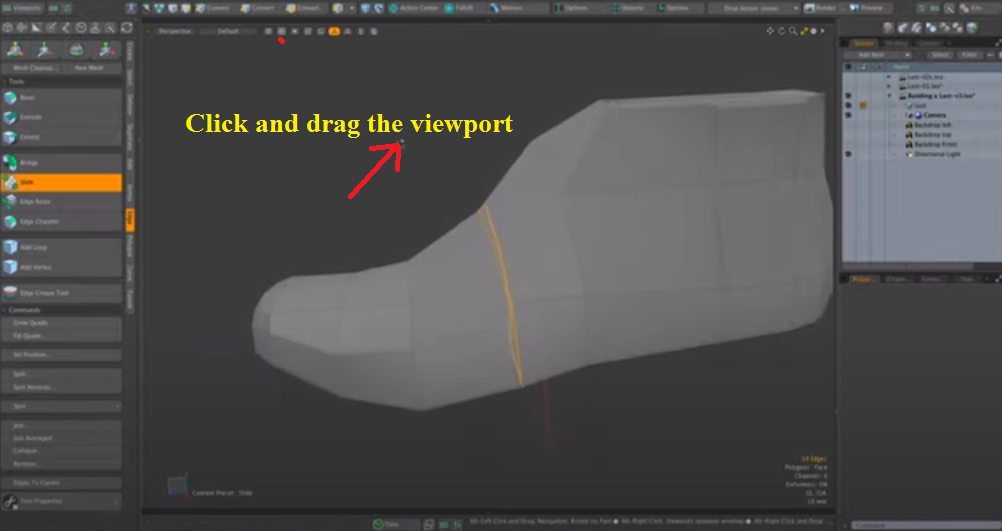
You can also click and drag the edges of a polygon in the viewport to move or change its contour.
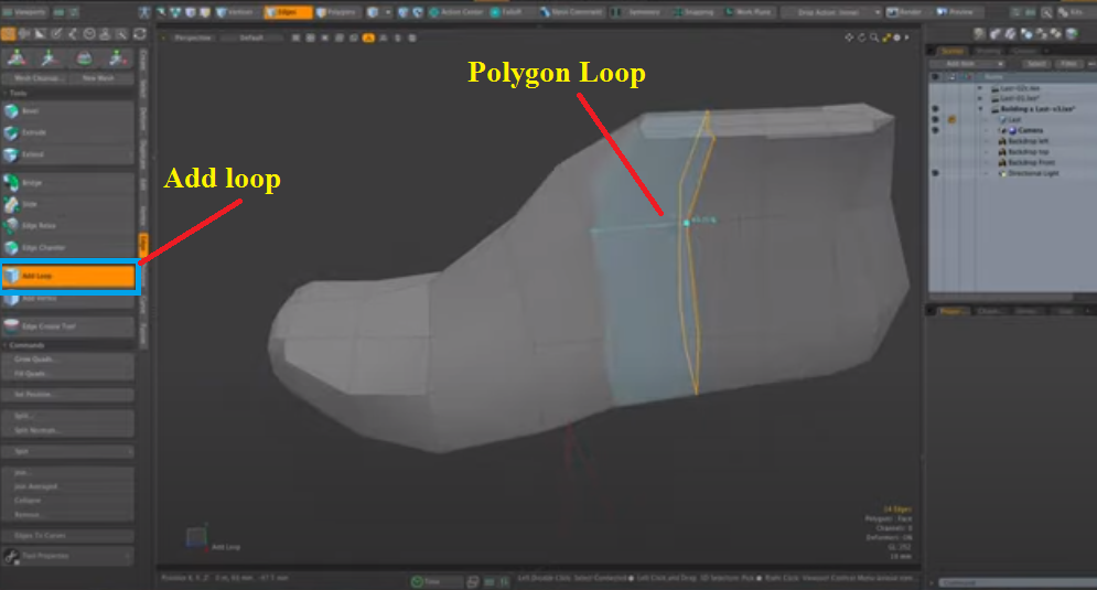
There are multiple methods for creating loops in Modo. We'll demonstrate our favorite method using the Add Loop tool.
To access this tool, press Shift+L and Left-click on the area you want to create a loop. We like to use this method because it's quick to adjust.
The Add Loop tool works like this:
Polygon Selection Mode: Clicking on an edge ring with the Add Loop tool (Shift+L) will create a new loop from that edge ring.
Edge Selection Mode: Clicking on an edge segment with the Add Loop tool (Shift+L) will create a new loop from that segment. If you hold down Shift, it will add a loop to both segments of the polygon border. Note that when adding loops in edge selection mode, you need to be careful not to select edges already part of an existing loop.
Another method is to highlight a polygon loop by right-clicking over an edge. It will cut when you click on that edge, allowing you to place it wherever you want along that perpendicular edge.
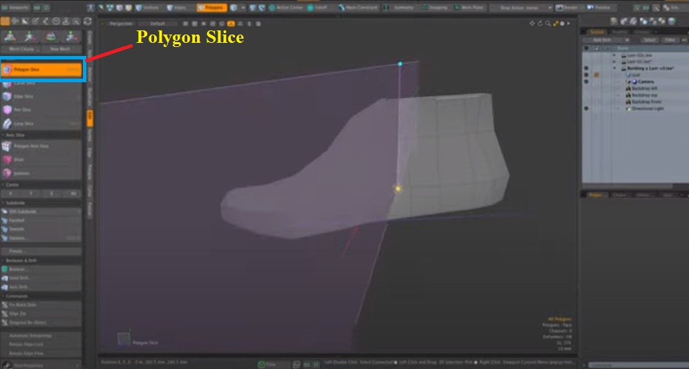
To use the Polygon Slice tool in Modo, select an object, then click on the Edit Tool > Polygon Slice button from the Mesh Tools (Polygons) tab.
Make sure you have a single polygon face selected and hit CTRL+SHIFT+C to get it centered in the viewport. Then, click and drag on a slice plane to cut through your model.
There are two cut modes: Cut Through (1) and Cut Partial (2), either of which can be selected from the top menu of the tool properties.
The Polygon Slice will give us a straighter edge cut. You can see it sliced a nice edge through the entire model.
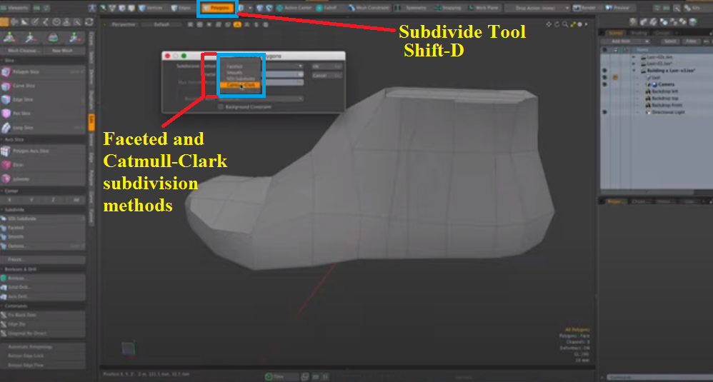
Modo has two different methods for subdivision surfaces (using the Subdivide tool): the faceted or Catmull-Clark subdivision methods. While the basic workflow is the same, both methods produce different results and are used for different reasons.
Faceted Method: The faceted subdivision method is more akin to repeated loop cuts. While this may appear to be a drawback, it can be useful in some cases. The most obvious benefit of using this method is that it's always faster than the Catmull-Clark method and often produces cleaner results when retopology is needed.
Another benefit of using this method over Catmull-Clark is using it on a mesh with no subdivision levels applied. It can help create better creases or edges that will not be smooth. More often than not, you will use the faceted subdivision method when creating models that have hard surface mechanical elements such as cars, planes, and buildings.
Catmull-Clark Method: The Catmull-Clark subdivision method smooths the model's curvature and produces a more organic result. The subdivision method means that this operation will soften all the hard edges created with the faceted subdivision method and produce a smoother result.
We'll also use the Subdivide tool. If we're in component mode, we can press the shift-D key to subdivide our model. You can either select faceted or Catmull-Clark subdivision methods in the drop-down menu. We'll be using those two. If you click faceted mode, you see it just divides every polygon in half in both directions.
Another tool we'll be using is the Element Move tool. We don't need to have anything selected; let's go over to the Deform Toolbox at the very top. If we don't have anything selected, we can mouse over a particular element in the viewport and move it by clicking and dragging that element.
This method is a really good way to nudge individual elements. It works with vertices, polygons, and edges. Right-click your mouse anywhere in the viewport, drag it to the right, and it will increase your influence on that tool. We can grab a bunch of polygons at the same time.
To decrease the size of a particular element, we can use the Element Push tool, which has the same effect. We can decrease the amount of influence, but if we bring it down to zero, it only affects that particular element. If we click on that option at the top, we see how it moves that selected element perpendicular to its plane.
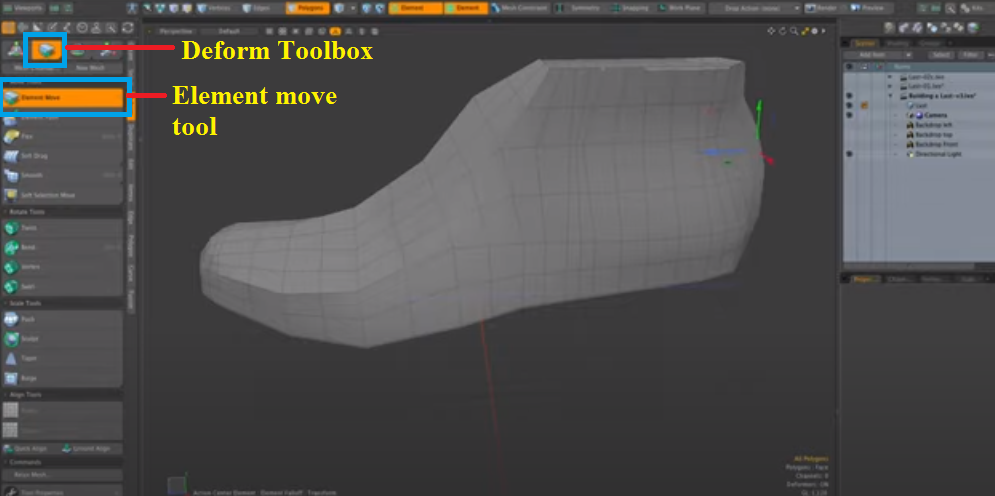
By clicking this polygon, you can see how it affects the other polygons in that direction. Now, we're going to increase the influence. Let's move that out and see how that works. It's a very intuitive tool.
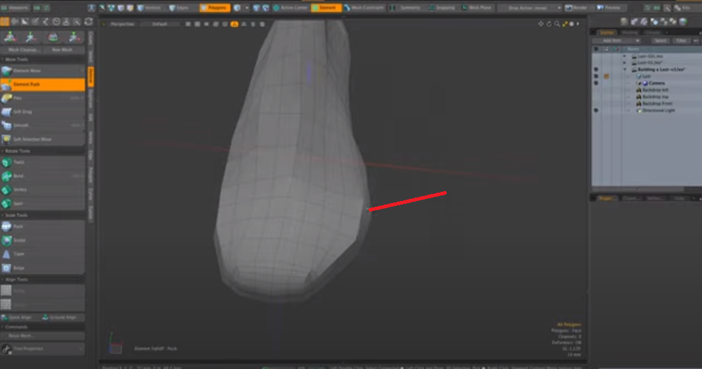
The Element Push tool is a flexible, powerful deformation tool that allows you to push or pull on the surface of your model. The main workflow for the Element Push tool is to select all the polygons you want to affect, then use the Element Push tool to move them in a direction.
Ensure you're in vertex sub-object mode to get started with the Element Push tool. Select the polygons you want to deform by using Element selection or Polygon selection. Because we're working in vertex sub-object mode, we can only affect vertices, so Modo automatically selects all the selected polygons.
By changing falloff modes, you can change how Modo affects vertices when using the Element Push tool. You can set this up by selecting the Properties tab below the 3D Viewport and opening up Tool Settings.
The falloff type determines how much each vertex moves from its original position. Falloff modes take effect from the center outwards, so a falloff type like Square will push as far away from the center as possible. In contrast, a type like Linear will push smoothly outwards from the center. The strength value determines how far each vertex moves from its original position.
In this case, you have to select one or more elements. You can click on the push tool and then click and drag. That will limit the push to just those particular elements.
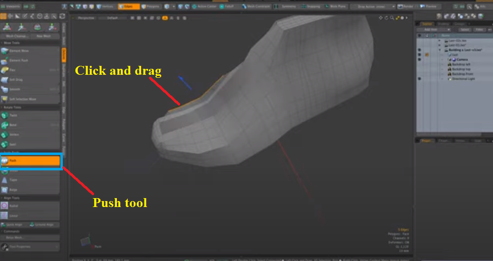
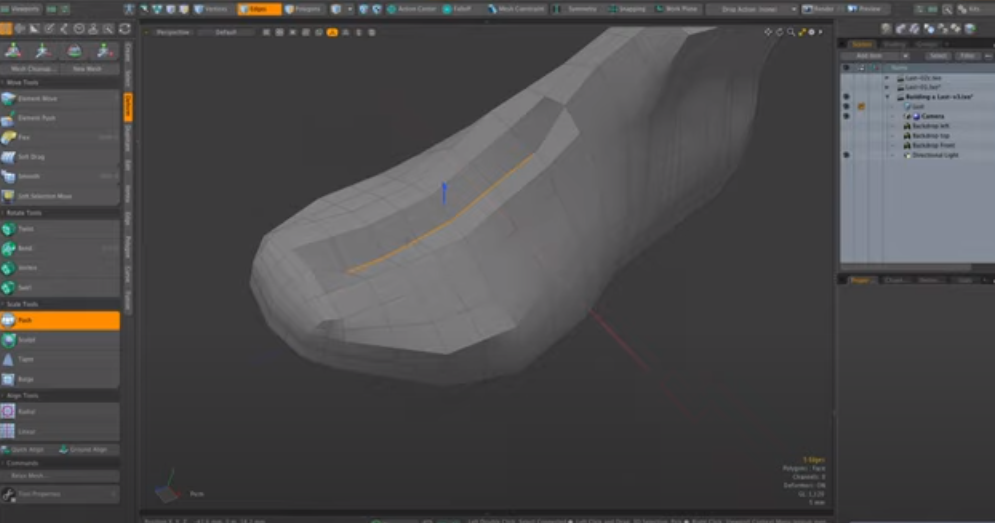
As you can see, it's moving those elements perpendicular to the plane of the surface normals that they're resting on there. These are the only tools we will use to build this model. It should be quite easy.
There are many tools available to design a product. The above mentioned tools in this article provide some examples of tools you can use, depending on the type of task or goal you have in mind when designing a product. When using design tools, it's important to stay organized.
With glTF, you can export a model to the p3d.in host. The result is a high-quality visualization with animation, physics, and interaction.
We hope you have enjoyed this article and can use some of the information shared here. We want to remind you that practicing is the best way to improve your workflow using these design tools. The more projects you tackle, the more familiar you will become with this program.